 EN
EN


What Steps Are Included In Custom Processing Of a Turbine Airfoil?
From a precision forging manufacturer's perspective, the quality gap between a custom turbine airfoil that delivers expected turbine performance and one that leads to premature replacement rarely traces to a single manufacturing step. It more often originates in early decisions — around drawing interpretation, material selection, and forging parameter control — that set the dimensional tolerance baseline for every turbine airfoil stage that follows.
Custom turbine airfoil processing involves a structured sequence of interdependent steps. Understanding each step — and what can go wrong between them — is essential for procurement teams, MRO service providers, and engineering departments evaluating a new turbine airfoil supplier or placing a first-time order for a non-standard profile.
Step 1: Engineering Drawing Review and Specification Alignment
The first step in custom turbine airfoil processing is a detailed review of the customer's engineering drawings. For non-standard, legacy, or retrofit turbine applications, this review determines whether the specified turbine airfoil profile, root geometry, and platform dimensions are achievable within the forging or machining process envelope.
This step surfaces any ambiguities in tolerance callouts, surface finish requirements, and material grade specifications before manufacturing begins. A turbine airfoil supplier that rushes this step tends to discover issues at final inspection, when rework costs and delivery delays become unavoidable. For customers supplying drawings of non-standard turbine airfoil profiles, the drawing review must also confirm that the forging die design can reproduce the specified leading edge and trailing edge geometry that directly governs aerodynamic performance.
Step 2: Material Selection and Raw Material Qualification
Turbine airfoils operate under extreme thermal and mechanical loading. The raw material, typically a nickel-based superalloy, titanium alloy, or stainless steel depending on the turbine stage, must be selected and verified before turbine airfoil processing begins.
Material selection for custom turbine airfoil processing is more nuanced than matching an alloy designation on paper. Superalloys and titanium alloys have inherently low machinability, which affects tool life and dimensional stability during subsequent machining. The alloy form, whether bar stock, billet, or pre-form, and its microstructural condition going into forging have a direct effect on the dimensional consistency and mechanical properties of the finished turbine airfoil — properties that ultimately determine turbine performance at the stage level.
Raw material qualification involves mill certificate review, chemical composition verification, and in some cases incoming mechanical property testing. Suppliers processing custom turbine airfoils for regulated applications — power generation, aero-derivative gas turbines — must maintain documented material traceability through the entire processing sequence.
Step 3: Precision Forging or Near-Net-Shape Preform Production
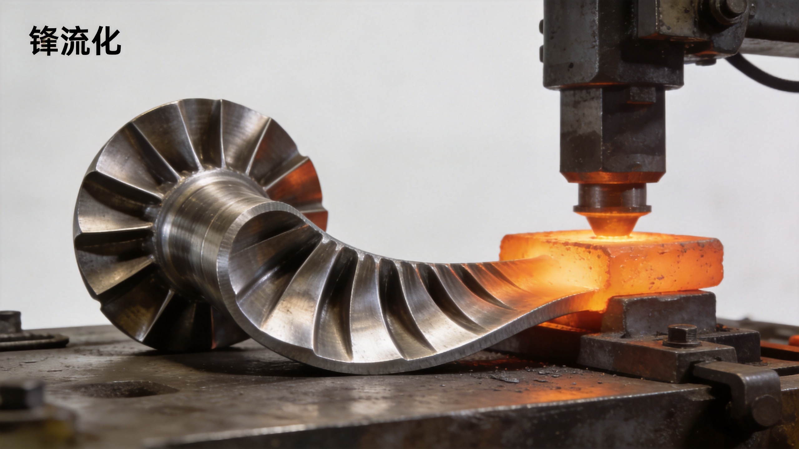
For custom turbine airfoil manufacturing where precision forging is the production route, die design and forging parameter setup are critical control points. The forging die must accurately reproduce the turbine airfoil cross-section across the full profile, including chord length, camber, and twist angle.
The dimensional allowance built into the forging step determines how much machining material remains on the turbine airfoil surface. Conventional forging allowances of several millimeters per surface require extensive CNC machining after forging, increasing lead time and cost per turbine airfoil. Low-allowance forging processes achieving turbine airfoil surface tolerances in the 0.1–1 mm range reduce the downstream machining burden — and since machining is where airfoil geometry errors most commonly accumulate, starting with a tighter forged profile improves overall dimensional consistency.
Process capability should be verified with dimensional checks at the forging stage, not deferred to final turbine airfoil inspection.
Step 4: CNC Machining of the Airfoil Profile and Root Geometry
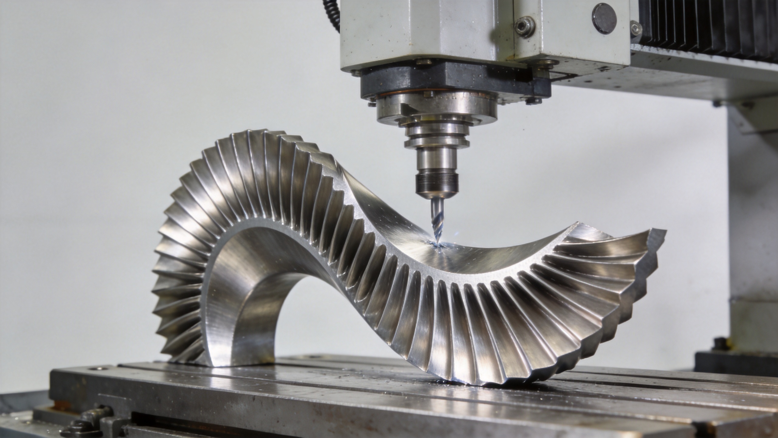
CNC machining is the step where the precision requirements of the turbine airfoil are realized in actual part dimensions. For complex turbine airfoil profiles, 5-axis CNC machining allows continuous tool contact with the curved airfoil surface, which is essential for holding tolerances of ±0.01 mm or tighter on precision aerodynamic surfaces.
Root geometry machining, including dovetail, fir-tree, and other attachment forms, requires separate programming and verification. The root interface determines how the turbine airfoil fits into the disc assembly, and dimensional errors here affect assembly clearance and vibration behavior. For customized turbine airfoil orders, root machining must be validated against the specific turbine disc interface dimensions, not assumed to match a generic reference.
Cooling holes, where specified, require drilling as small as 0.3 mm diameter in high-temperature superalloys, which demands specialized tooling and rigorous in-process verification.
Step 5: Surface Treatment and Protective Coating Application
Surface treatment for custom turbine airfoils encompasses shot peening, vibration finishing, sand blasting, and protective coating application. The specific treatment sequence for each turbine airfoil depends on its operating environment, thermal exposure, and the applicable turbine OEM specification.
Coating integrity is a step that deserves more attention in procurement discussions. The turbine airfoil material grade may be correctly verified, but coating adhesion quality, meaning the bond between the thermal barrier or oxidation-resistant coating and the base metal, can degrade if surface preparation is inconsistent. This failure mode produces turbine airfoils that appear dimensionally correct on incoming inspection but develop coating delamination after limited service, undermining overall turbine performance.
Shot peening, when specified, introduces compressive residual stresses in the turbine airfoil surface layer to improve fatigue resistance. Process parameters — shot size, intensity, and coverage — should be documented and verified against drawing callouts.
Step 6: Aerodynamic Test Simulation and Dimensional Inspection
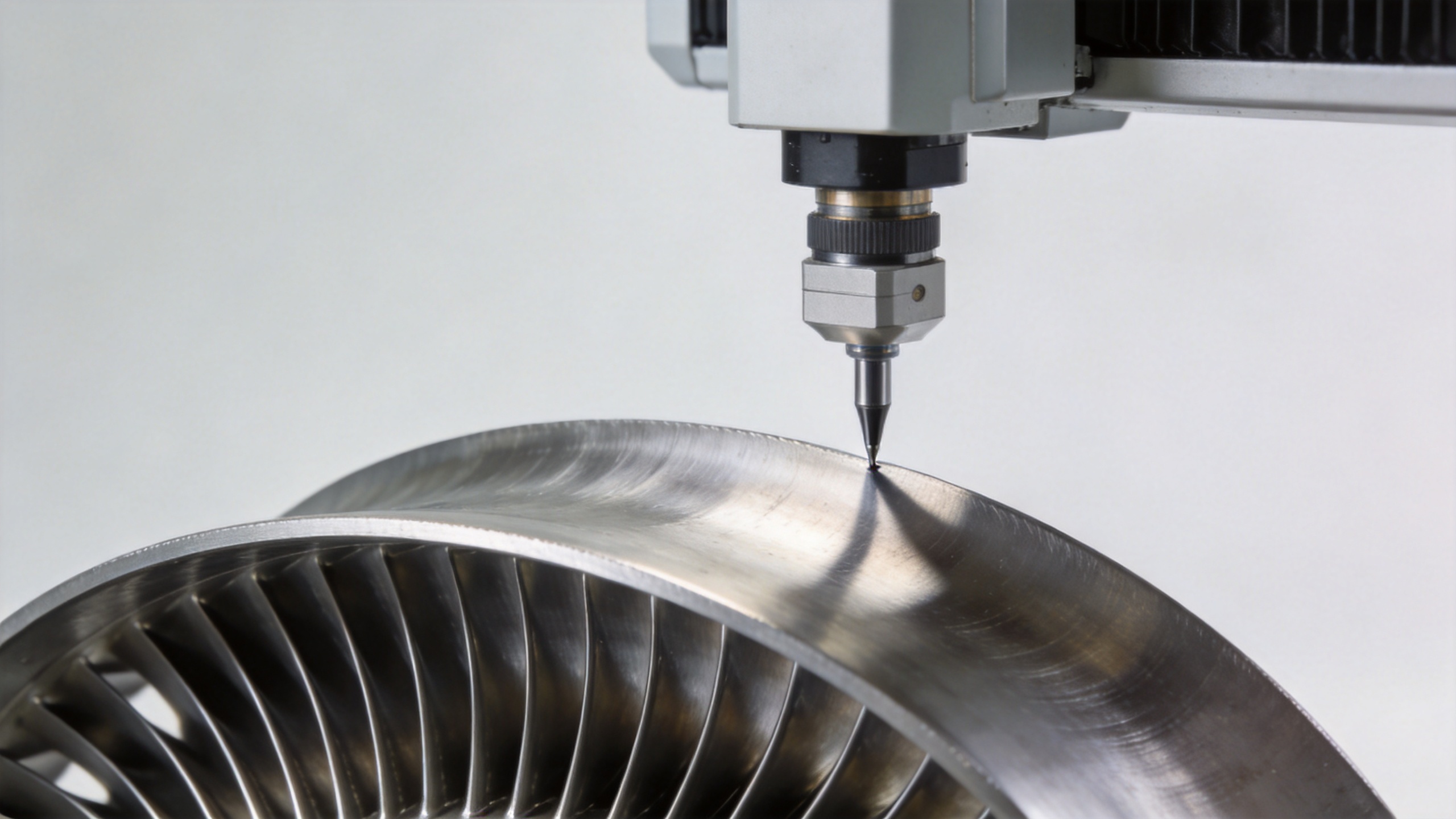
Dimensional inspection for a custom turbine airfoil goes beyond pass/fail checks on a few linear dimensions. The turbine airfoil profile must be verified against the customer's drawing across multiple cross-section measurement planes, and results should be compared against the coordinate data that defines the aerodynamic surface.
CMM (Coordinate Measuring Machine) inspection produces an overlay comparison of the measured turbine airfoil profile against nominal drawing coordinates. Leading edge and trailing edge geometry require particular attention; these regions most directly affect aerodynamic test behavior when the turbine airfoil enters service and are most prone to dimensional deviation from forging die wear or machining tool path errors.
For first-article inspection of a custom turbine airfoil order, dimensional reports should include full profile data across all specified measurement planes. Some procurement programs require aerodynamic test or flow bench validation to confirm that turbine performance targets are met by the custom turbine airfoil geometry before volume production is released.
Step 7: Quality Documentation and Delivery Preparation
The final step in custom turbine airfoil processing is assembling the quality documentation package. For turbine airfoils supplied to power generation operators or MRO programs, this typically includes the dimensional inspection report, material test certificates, process records covering forging, heat treatment, and coating, and any applicable special process certifications.
Complete documentation supports the customer's incoming inspection and installation qualification process. A documented processing record also makes it easier to replicate a successful first turbine airfoil order and to investigate any turbine performance anomaly that surfaces after installation.
Each step in the custom turbine airfoil processing sequence — from drawing review through final documentation — produces a verified output that feeds forward into the next manufacturing stage. For procurement teams and MRO service providers qualifying a turbine airfoil supplier for the first time, understanding how a supplier manages each step, and what process records are available at each stage, provides a more reliable qualification basis than dimensional verification on a single turbine airfoil sample alone.
For custom turbine airfoil inquiries, including non-standard and legacy turbine profiles, contact Navi Power Technology Co. Ltd. at [email protected] or visit www.compressorblade.com.