 EN
EN

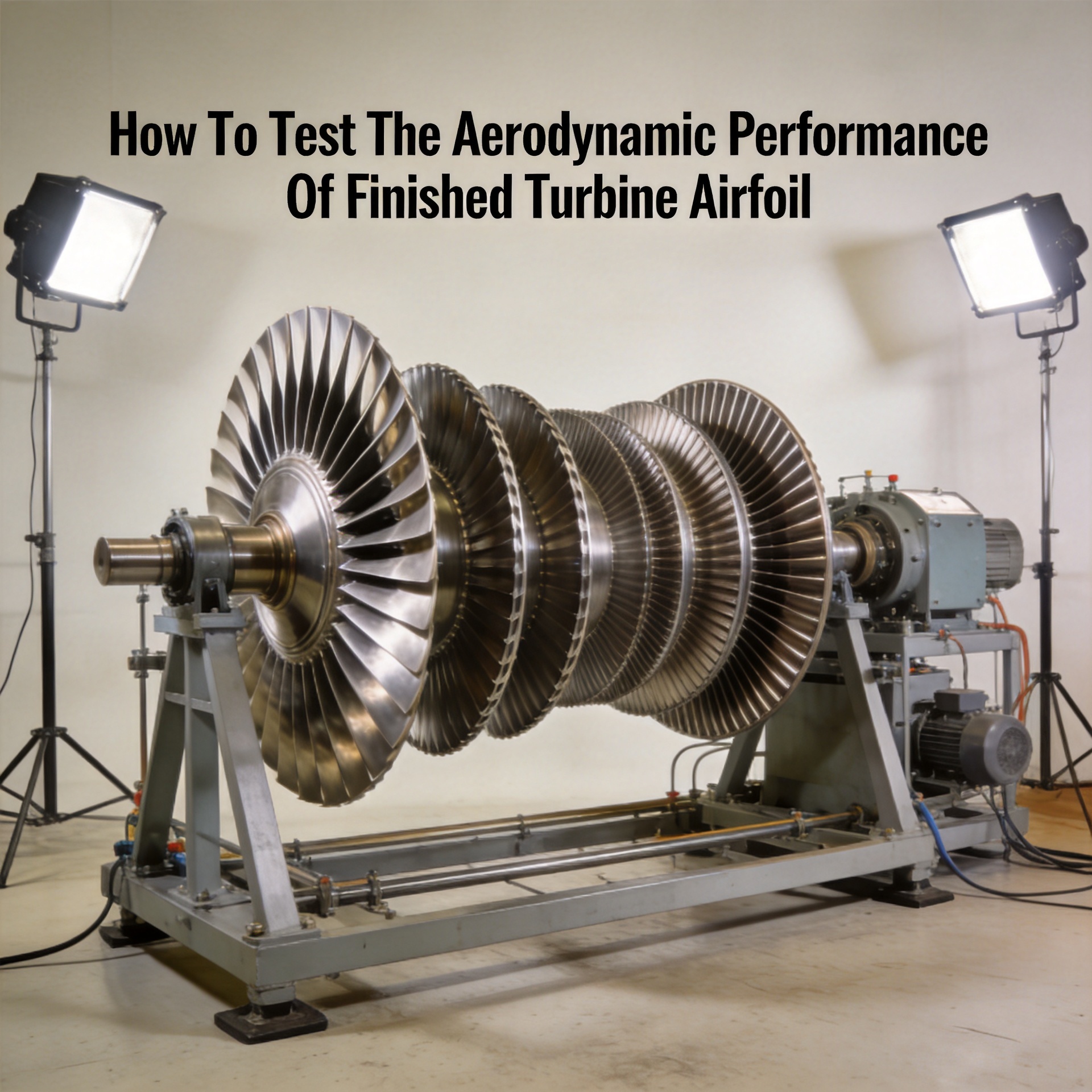
How To Test The Aerodynamic Performance Of Finished Turbine Airfoil?
From an aerodynamic engineering standpoint, validating a finished turbine airfoil requires more than dimensional inspection — manufacturing precision must translate into measurable fluid-dynamic outcomes. If your priority is ensuring a precision-forged compressor blade will deliver its rated pressure ratio in service, your aerodynamic test protocol matters as much as the dimensional report that came with the part.
This guide covers the primary test methods, key parameters, and how to interpret results for finished gas turbine airfoils — whether accepting delivery from a supplier, qualifying a new forging source, or conducting MRO-driven validation.
Why Post-Manufacturing Aerodynamic Testing Matters
Dimensional inspection confirms that a turbine airfoil meets its drawing geometry — chord length, camber, thickness distribution, and edge radii. But geometry alone does not guarantee aerodynamic performance. Surface finish, micro-level profile deviations, and leading-edge condition all influence flow behavior in ways coordinate measurements cannot fully capture. Matching alloy grade and profile geometry on paper does not automatically translate to equivalent service life or turbine performance in your specific operating environment.
For critical compressor and turbine stages, aerodynamic testing provides the data type that directly correlates with stage efficiency and total pressure recovery — a gap that running blades through dimensional-only acceptance does not address.
Core Aerodynamic Parameters to Measure
1. Total Pressure Loss Coefficient
The total pressure loss coefficient quantifies energy dissipation as flow passes through the blade cascade — the ratio of total pressure drop across the blade row to inlet dynamic pressure. For precision-forged compressor blades, values outside the design-point range typically indicate surface roughness issues, profile deviations, or leading-edge damage requiring investigation before installation.
2. Flow Turning Angle
The flow turning angle measures how effectively the blade deflects the incoming gas stream to the intended exit angle. Deviations from the design value affect adjacent blade row matching and stage loading. Even 1 to 2 degree deviations can compound into measurable efficiency losses across compressor stages.
3. Lift and Drag Coefficients
Lift and drag coefficients characterize blade aerodynamic loading and resistance. The lift-to-drag ratio is the primary indicator of aerodynamic quality at a given incidence. Comparison against CFD-derived coefficient curves at design incidence gives a direct quality verdict.
4. Pressure Distribution Along the Airfoil Surface
Surface pressure distribution, measured via pressure taps on cascade test articles, reveals separation bubbles, premature flow transition, and suction-side loading inconsistencies. Comparing measured distributions against CFD predictions validates finished turbine airfoil aerodynamic performance at production qualification level.
Primary Test Methods for Finished Turbine Airfoils
Linear Cascade Wind Tunnel Testing
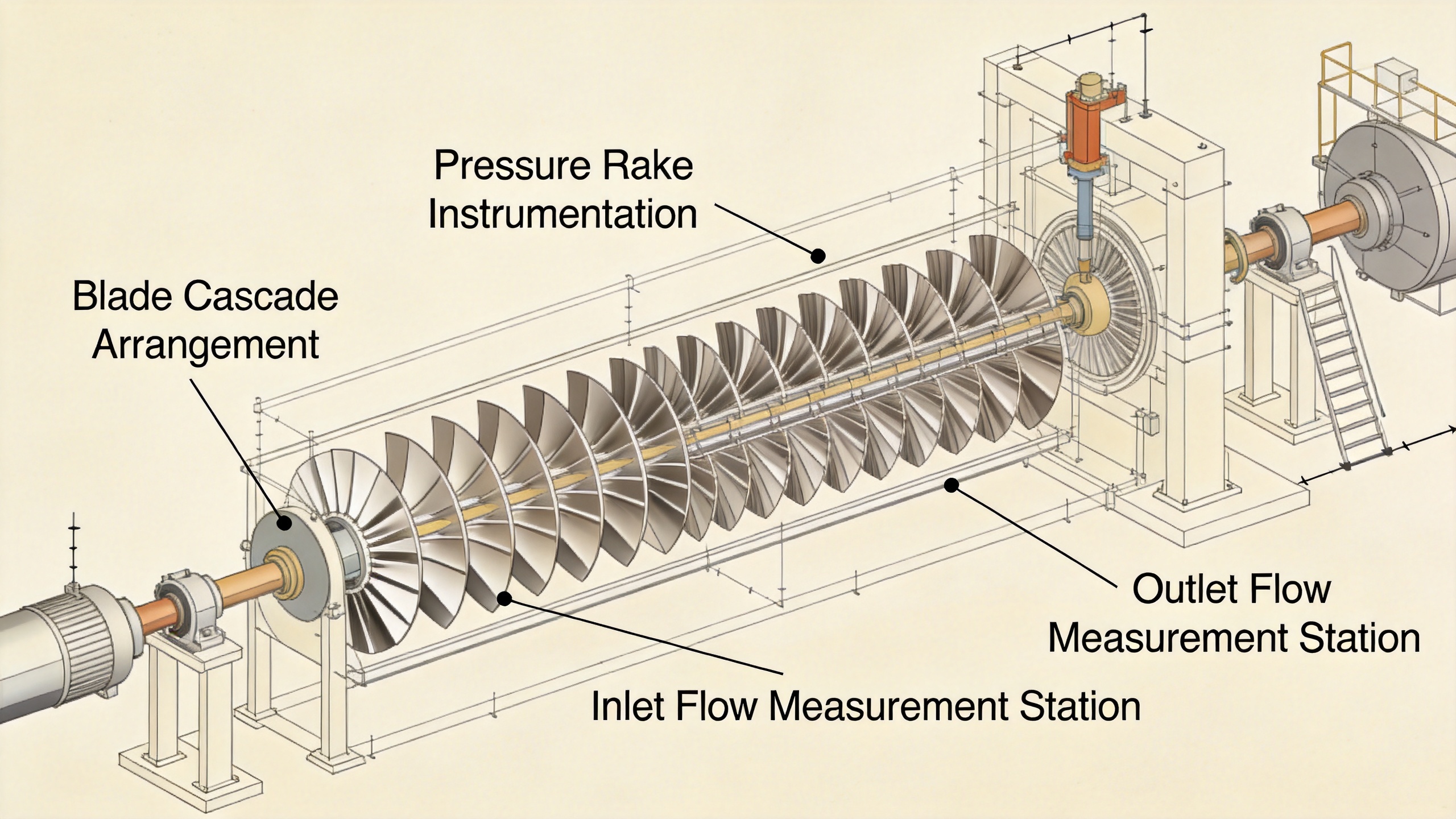
The linear cascade wind tunnel is the industry-standard method for aerodynamic performance evaluation of compressor and turbine blade profiles. A row of 7 to 11 blades is arranged in a planar cascade within a wind tunnel test section. Instrumented pitot-static rakes upstream and downstream measure inlet and exit total pressure, static pressure, and flow angle.
Three independent repeated aerodynamic test runs are standard practice to eliminate instability effects and produce statistically valid results. For gas turbine compressor blades, Mach numbers of 0.3 to 0.8 cover the relevant operating range of most industrial and power generation applications. Cascade testing is practical for supplier qualification batches of 5 to 20 blades.
Rotating Rig Testing
Rotating rig tests mount blades in a fully representative annular stage configuration. This is the most representative aerodynamic test environment but the most expensive and time-intensive. Rotating rig testing suits new blade design validation or first-article forging qualification, not routine production batch acceptance.
CFD-Informed Dimensional Cross-Check
Where full cascade testing is not economically justified for every batch, high-fidelity 3D scanning combined with CFD analysis of the as-measured geometry provides a cost-effective intermediate step. If the predicted turbine performance falls within tolerance of design intent, the batch can proceed without physical cascade testing.
Relying on incoming geometric inspection alone to catch aerodynamic performance issues is less effective than understanding a supplier's forging process capability. Suppliers with tight dimensional tolerance control — such as precision forging achieving sub-millimeter tolerances — typically produce blades with more consistent turbine performance across batches.
Setting Up the Aerodynamic Test: Practical Steps
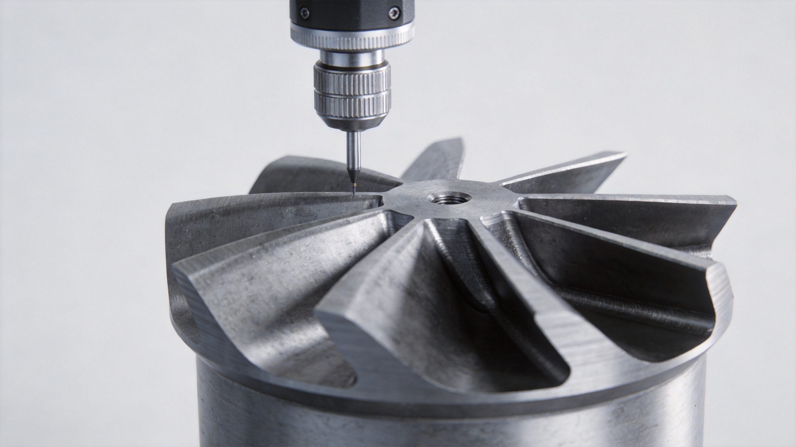
- Dimensional pre-inspection. Confirm the finished turbine airfoil meets drawing tolerances before cascade testing. Leading-edge damage correlates with aerodynamic performance degradation — catching out-of-spec geometry early saves test time.
- Define inlet conditions. Set Mach number, Reynolds number, and turbulence intensity to match the design operating point. For industrial gas turbine compressor blades: Reynolds 300,000–1,000,000, Mach 0.4–0.7 at cascade inlet.
- Instrument the test section. Install total pressure rakes and flow angle probes at one chord-length upstream and downstream. Use 15 to 20 probe positions to capture wake loss distribution adequately.
- Run three independent repeat tests. Average results to reduce random measurement uncertainty on loss coefficient readings.
- Compare against reference data. Accept if total pressure loss coefficient is within 5 percent of design datum and flow turning angle deviation is within 0.5 degrees at design incidence.
Interpreting Results and Making Acceptance Decisions
When evaluating turbine performance from cascade test data, the question is not just which turbine airfoil performs most efficiently under ideal conditions, but which one degrades most predictably under real-world stress. A blade delivering consistent pressure recovery over thousands of hours is more valuable than one peaking higher but showing sensitivity to incidence variation.
Key aerodynamic test acceptance criteria:
- Total pressure loss coefficient within 5 percent of design datum across the incidence sweep.
- Flow turning angle deviation less than 0.5 degrees at design incidence.
- No laminar separation bubbles on suction surface at design Mach number.
- Lift-to-drag ratio within 8 percent of design-intent polar at operating incidence.
Building these criteria into supplier quality agreements provides an enforceable turbine performance standard for finished turbine airfoils beyond dimensional reports alone.
Connecting Test Data to Supply Chain Decisions
For power and energy operators and MRO service providers, aerodynamic test data from production batch samples is more actionable than per-part dimensional certificates. Suppliers providing cascade test correlation data — showing how manufacturing consistency maps to aerodynamic performance consistency — offer a meaningfully stronger quality proposition.
Request cascade test data or CFD-informed 3D scan analysis as part of your qualification package. For ongoing procurement, periodic batch aerodynamic testing ensures turbine performance expectations are met in service rather than discovered as shortfalls after installation.
Conclusion
Testing turbine airfoil aerodynamic performance requires moving beyond dimensional inspection to direct measurement of pressure loss, flow turning, and surface loading. The linear cascade wind tunnel is the standard for production-representative aerodynamic testing. Combined with pre-inspection and CFD cross-checks, a structured protocol ensures finished blades deliver the turbine performance your application demands.