 EN
EN

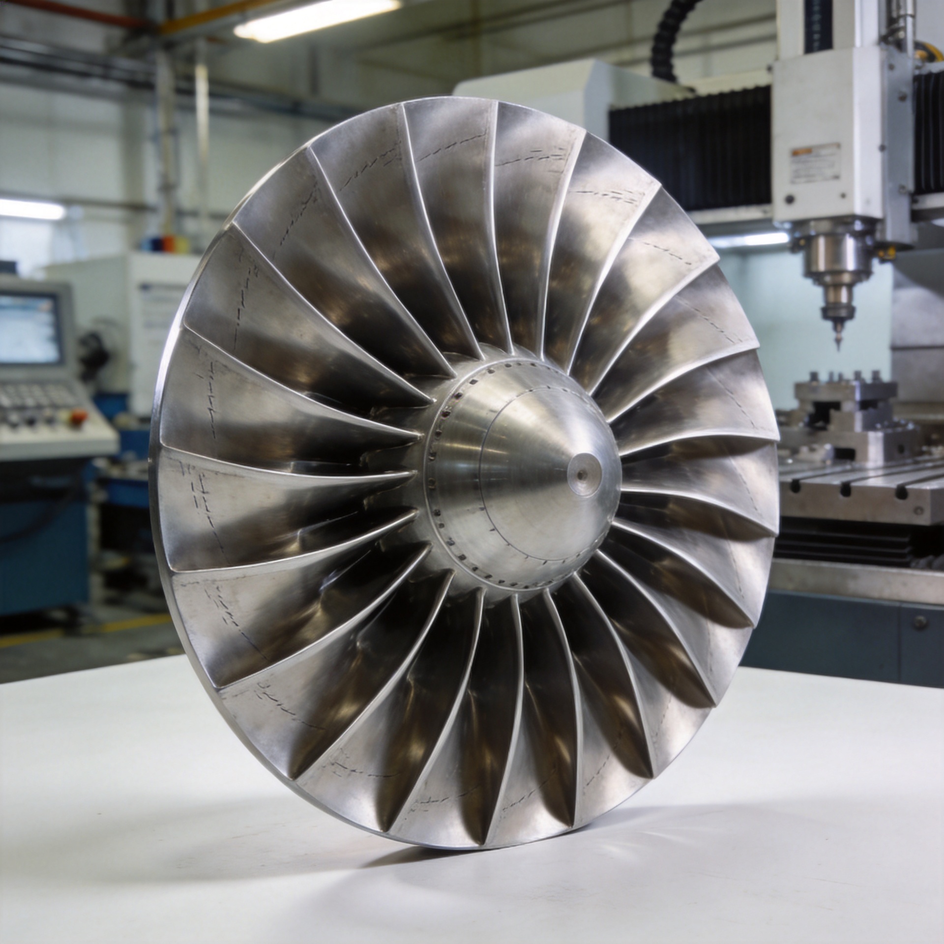
What Machining Technology Is Used For Smooth Turbine Airfoil Surface?
From a gas dynamics engineering perspective, the surface quality of a turbine airfoil is not just a finishing detail; it directly determines how efficiently the blade converts energy. Even minor deviations in surface roughness alter the boundary layer behavior of airflow across the blade surface, increasing profile losses and reducing stage efficiency. This is why airfoil surface machining is treated as a critical engineering discipline rather than a cosmetic production step.
The accepted threshold for turbine airfoil surface roughness is Ra ≤ 0.8 μm in most applications, with some high-pressure compressor stages requiring Ra as low as 0.4 μm. Reaching these values, while maintaining dimensional tolerances of ±0.02–0.05 mm along the blade profile, requires a carefully sequenced combination of machining technologies.
Why Surface Finish Matters for Turbine Airfoil Performance
Research and field data both confirm the aerodynamic penalty of a rough turbine airfoil surface. A low-pressure turbine stage with a characteristic surface roughness of around 2.2 μm Ra — a common result after blasting and aging treatment — can lose measurable efficiency compared to a precision-finished surface. For compressor stages in industrial gas turbines, where cumulative stage losses directly reduce turbine output, the difference between a 1.6 μm Ra surface finish and a 0.4 μm Ra finish can translate to noticeable fuel consumption differences over a full operating season.
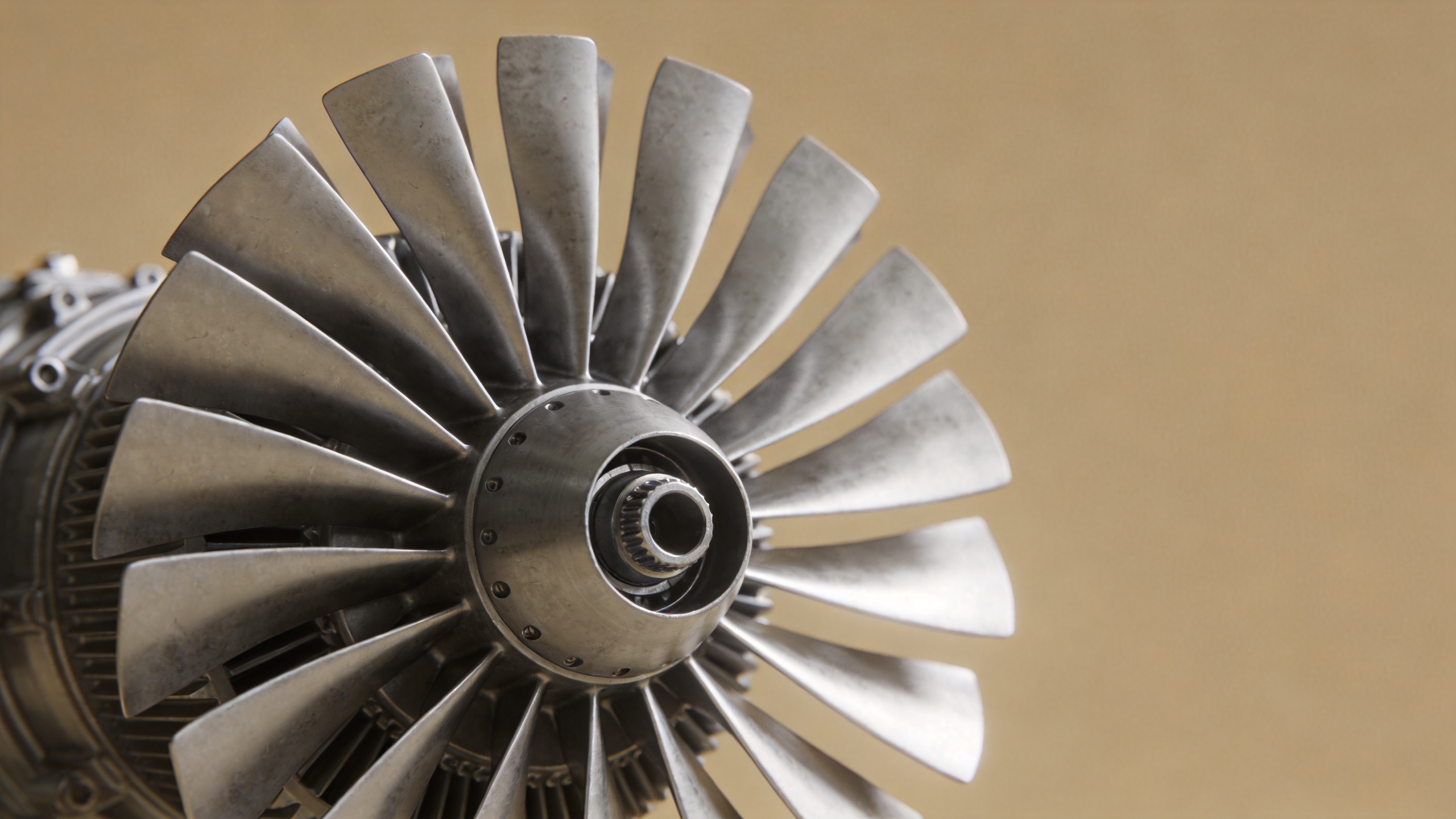
Understanding which machining technology produces which surface outcome is therefore a procurement and engineering decision, not just a shop-floor specification. Before deciding what finish standard to demand from a blade supplier, it is worth asking: have you confirmed the specific Ra value required for your turbine airfoil model, or are you applying a general specification borrowed from a different turbine application?
Core Machining Technologies for Smooth Turbine Airfoil Surfaces
5-Axis CNC Milling: The Starting Point for Airfoil Profile Processing
Modern turbine airfoil machining is built around the 5-axis CNC machining center, which uses three linear axes and two rotational axes to maintain the cutting tool at the optimal angle relative to the complex curved airfoil surface throughout the entire cutting path. This eliminates the "shadow area" problem of conventional 3-axis milling, which cannot access concave portions of the blade geometry without part repositioning.
Within 5-axis CNC blade machining, two distinct cutting strategies are applied depending on the blade geometry and the specific blade design requirements:
- Flank milling uses the side of the cutting tool to machine the turbine airfoil surface in sweeping passes. This approach is highly efficient and produces good surface continuity, making it the preferred strategy for components with larger radii of curvature and relatively gentle profile transitions. Industrial compressor blades in the mid and rear stages are typical candidates for flank milling.
- Point milling uses the tool tip to trace the turbine airfoil surface layer by layer. The flexibility of this approach makes it suitable for complex geometries with small-radius regions, tight trailing edges, or highly twisted profiles — characteristics common in aerospace engine high-pressure blades.
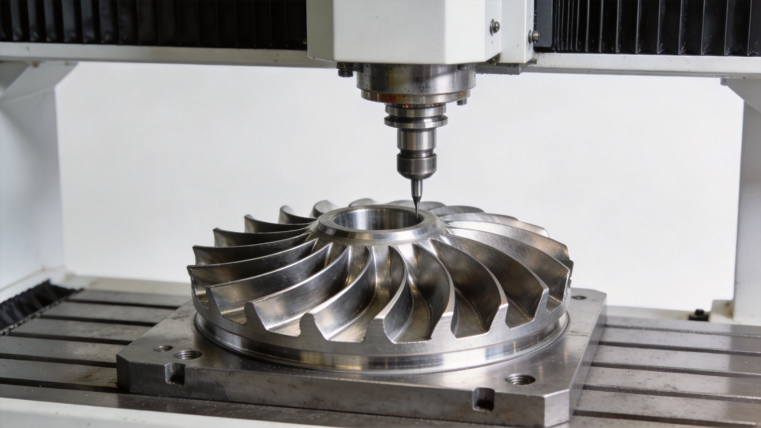
After 5-axis CNC milling, the typical surface roughness achieved is in the 1.6–3.2 μm Ra range. This is sufficient for profile accuracy but does not yet meet the Ra ≤ 0.8 μm threshold required for optimal airfoil performance. Further surface processing is required.
CNC Creep-Feed Grinding: Precision Turbine Airfoil Surface Refinement
Creep-feed grinding follows the CNC milling stage and is specifically suited for turbine airfoil surface refinement. Unlike conventional reciprocating grinding, creep-feed grinding moves the workpiece slowly through a deeply engaged grinding wheel in a single pass. This process is well-matched to the curved blade geometry and achieves surface roughness in the Ra = 0.2–0.4 μm range — well below the Ra ≤ 0.8 μm threshold for most turbine airfoil applications.
Beyond surface finish, creep-feed grinding also corrects minor dimensional deviations left over from the milling stage. In practice, the tolerance accumulation from multi-step blade machining can push the airfoil profile slightly outside the ±0.02–0.05 mm specification window. Grinding provides both the surface improvement and a final profile correction, ensuring the component meets dimensional requirements after all processing steps.
If your priority is achieving a tightly controlled surface finish across a full blade batch, you should focus first on grinding process consistency rather than only the nominal Ra specification — blade-to-blade variation within a batch has different performance implications than a single out-of-spec piece.
Polishing and Final Turbine Airfoil Surface Finishing
For applications requiring the finest turbine airfoil surface quality — particularly aerospace engine components or high-pressure compressor blades in demanding operating environments — a polishing step follows grinding. The polishing process, whether performed by robotic systems or specialized CNC turbine airfoil finishing machines, removes residual grinding marks and achieves Ra values below 0.4 μm.
Industrial turbine airfoil polishing systems with 6-axis CNC capability can process the full airfoil geometry including leading and trailing edge transition zones. Modern systems integrate coolant-based processes to prevent thermal loading during airfoil finishing, which matters because heat accumulation can alter surface hardness in titanium and nickel alloy blades.
In practice, the lesson from rework cycles in blade production is that an unspecified surface roughness tolerance in the procurement document allows acceptable-but-suboptimal finish variation. That variation only becomes visible when aerodynamic test data is compared across production batches — by which point the cost of correction is significant.
Machining Sequence and Its Impact on Turbine Airfoil Profile Processing
Achieving a smooth airfoil surface is the outcome of a deliberate process sequence, not the result of any single technology. The standard airfoil profile processing sequence follows a clear logic:
- 5-axis CNC milling establishes the near-net turbine airfoil geometry with correct profile dimensions and chord length.
- Creep-feed grinding refines the turbine airfoil surface to within the Ra ≤ 0.8 μm target and corrects dimensional deviations.
- Polishing achieves final surface quality for turbine airfoil applications where Ra < 0.4 μm is required.
- Dimensional inspection — including CMM or 3D scanning of key turbine airfoil cross-sections — verifies that the finished profile remains within specification after all blade machining steps.
One pattern that shows up repeatedly in turbine airfoil sourcing: the material grade and nominal dimensional tolerance are verified at incoming inspection, while the surface roughness measurement across the full blade profile is not included as a documented acceptance criterion. The profile matched on paper, but the surface finish on the leading edge region had not been measured — and that is where the performance gap originated.
Matching Blade Machining Capability to Your Turbine Airfoil Application
The right blade machining technology combination depends on the specific turbine airfoil application requirements. For industrial gas turbine compressor blades operating in clean inlet conditions, 5-axis CNC milling followed by creep-feed grinding typically delivers the required turbine airfoil surface quality. For aerospace engine applications or turbine airfoil blades in high-particulate environments where surface erosion is a factor, full polishing to Ra < 0.4 μm is worth the additional processing cost.
Standard visual and dimensional inspection at goods receipt catches surface-level geometry deviations, but subsurface machining-induced stress concentrations that can drive later fatigue cracking typically require non-destructive testing to detect — a distinction that becomes relevant when qualifying a new turbine airfoil supply source.
Navi Power Technology specializes in precision forged compressor blades with low-allowance turbine airfoil profiles. Our patented forging process delivers airfoil dimensional tolerances of 0.1–1 mm near-net, reducing the machining stock that downstream turbine airfoil profile processing needs to remove and contributing to final surface quality consistency. For procurement engineers evaluating blade supply for power generation or MRO applications, we welcome technical specification discussions based on your specific turbine airfoil stage requirements.
Contact us at [email protected] or visit www.compressorblade.com for more information.