 EN
EN

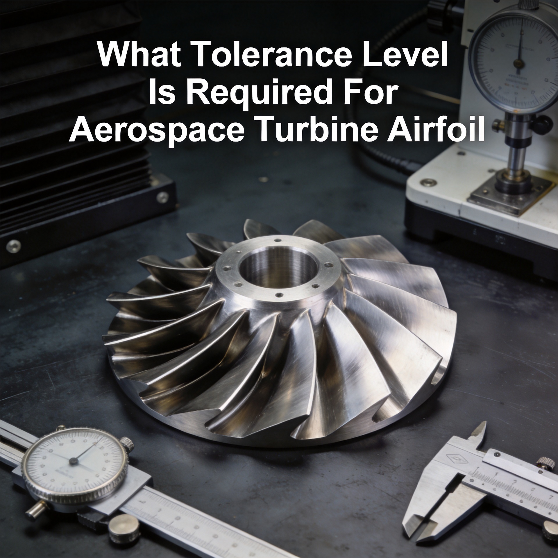
What Tolerance Level Is Required For Aerospace Turbine Airfoil?
Defining the correct tolerance level for an aerospace turbine airfoil is one of the more consequential decisions in compressor blade procurement and qualification. A turbine airfoil operating in a gas turbine compressor must meet precise dimensional requirements — beyond simply passing inspection — to deliver the aerodynamic performance the stage design depends on. Understanding these requirements, and the aerospace standard frameworks that govern them, is the starting point for any serious qualification program.
Airfoil precision matters because compressor efficiency is sensitive to geometric deviation. A turbine airfoil with profile errors that appear minor on an inspection report can shift the incidence range of a compressor stage or change leading edge boundary layer behavior in ways that reduce surge margin. The challenge for procurement engineers is connecting abstract tolerance numbers on a drawing to their real aerodynamic consequences.
Core Dimensional Tolerance Parameters for Aerospace Turbine Airfoils
Aerospace turbine airfoil tolerance specifications define requirements across several distinct geometric parameters. Each has different aerodynamic sensitivity and different consequences when out of specification. Evaluating airfoil precision means understanding all of them, not just the most visible dimensions.
1. Airfoil Profile Tolerance
Profile tolerance governs how closely the cross-sectional shape of a turbine airfoil matches the design intent at each measurement station. In aerospace applications, profile tolerances for compressor blades are typically specified as a band, ranging from ±0.1 mm for high-pressure stages to ±0.5 mm for lower-pressure stages. Airfoil precision at the profile level directly affects local boundary layer behavior and, at off-design conditions, can produce measurable efficiency loss even when the deviation is within tolerance band limits. Tighter airfoil precision requirements are standard for aero-engine compressor stages operating at high pressure ratios.
2. Leading Edge and Trailing Edge Geometry
Leading edge and trailing edge radii receive separate, tighter tolerances in most aerospace standard turbine airfoil specifications. The leading edge radius of a turbine airfoil determines how well the blade handles incidence variation: a blunted leading edge changes the incidence range and affects compressor stability at off-design conditions. Trailing edge thickness of a turbine airfoil affects trailing edge losses, which compound across multiple compressor stages and reduce overall cycle efficiency.
Maintaining leading and trailing edge geometry is one of the most demanding airfoil precision requirements in forged blade manufacturing. Conventional forging processes leave significant material allowance in these zones, requiring machining that can introduce geometry variation. Low-allowance forging processes capable of holding tolerances in the 0.1–1 mm range, such as those used by specialized compressor blade manufacturers, reduce the post-forging machining requirement and lower the risk of geometry deviation at these aerodynamically sensitive locations.
3. Chord Length, Span, and Twist Angle
Chord length tolerance for an aerospace turbine airfoil is generally specified in the range of ±0.5 mm to ±1.0 mm. Span (blade height) tolerance affects tip clearance when assembled, so it is verified both independently and in context of the stage build. Airfoil twist describes how the section angle varies from root to tip; for most compressor blades, twist tolerances are specified in angular units, commonly ±0.2° to ±0.5° across the span. Twist and stagger angle errors interact directly with the designed incidence angles at each radial station, reducing surge margin in ways that do not appear in individual blade inspection but show up during full-stage aerodynamic testing.
4. Surface Roughness
Surface roughness is a separate but closely related requirement for aerospace turbine airfoil applications. Most aerospace standard specifications for compressor blades require Ra values in the range of 0.8–3.2 μm on aerodynamic surfaces, with tighter requirements at the leading edge zone. Surface roughness above specification increases skin friction losses and promotes earlier boundary layer transition, degrading both compressor efficiency and surge margin.
Aerospace Standards Governing Turbine Airfoil Tolerance
Several standard frameworks define the quality and measurement requirements for aerospace turbine airfoil components:
- AS9100 – The quality management aerospace standard for manufacturing organizations. AS9100 mandates that dimensional requirements for each turbine airfoil are defined, controlled, and verified through documented processes. Any credible aerospace compressor blade supplier requires AS9100-aligned quality management.
- ASME Y14.5 – The geometric dimensioning and tolerancing (GD&T) standard used on aerospace blade drawings. Profile tolerances, datum structures, and measurement references for a turbine airfoil are expressed in ASME Y14.5 notation.
- AMS Material Specifications – The Aerospace Material Specifications series defines material grade requirements, heat treatment, and surface treatment for blades. While AMS specifications don't set airfoil precision geometry tolerances directly, they govern the manufacturing process parameters that affect how final geometry is achieved and maintained.
- OEM Drawing Specifications – In procurement practice, the governing aerospace standard for each turbine airfoil is the OEM drawing package. These drawings specify the exact tolerance values, measurement methods, and acceptance criteria for each turbine model and stage position, taking precedence over generic standards.
Precision vs. Cost: Understanding the Trade-Off
A common assumption in turbine airfoil procurement is that tighter tolerance equals better performance, and that the tightest achievable airfoil precision is automatically the right specification. In practice, tolerance allocation in aerospace blade manufacturing involves a real cost and delivery trade-off. Research on turbine blade tolerance optimization documents how tighter tolerances increase both scrap rates and inspection overhead, affecting production cost in ways that must be weighed against the marginal aerodynamic benefit.
The practical implication: turbine airfoil tolerance requirements should match what the aerodynamic analysis actually requires, not an aspirational airfoil precision level beyond what the stage design demands. Engineering pre-sales support, where a supplier reviews your drawing package and confirms whether the stated tolerances fall within their process capability, is a genuine value-add in aerospace standard qualification, not a formality.
Verifying Turbine Airfoil Tolerance Compliance
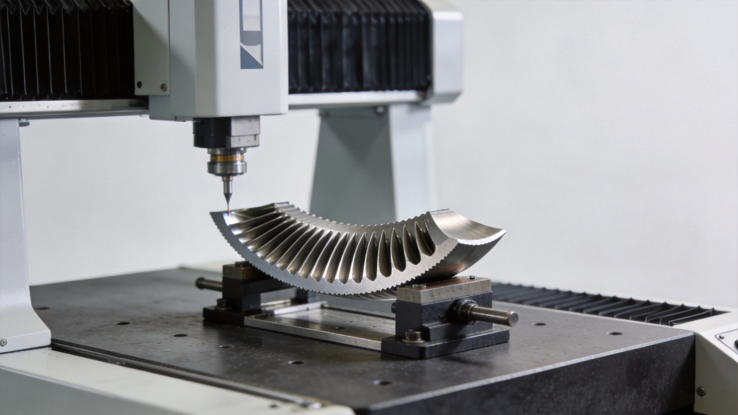
For incoming inspection of an aerospace turbine airfoil, two-dimensional cross-section fitting and three-dimensional surface scanning are standard verification methods. Two-dimensional fitting identifies profile tolerance compliance at specific measurement stations defined in the drawing. Three-dimensional scanning captures the full turbine airfoil surface and generates a color deviation map against nominal CAD geometry, providing comprehensive airfoil precision verification across the full aerodynamic surface.
Both methods require batch-level dimensional inspection reports documenting actual measured values against drawing tolerances for each key geometric parameter. For aerospace qualification programs, a first-article inspection report (FAIR) covering all dimensional, material, and process requirements provides the foundation for production approval. Suppliers who provide CMM or 3D scanning reports as standard documentation per delivery batch are demonstrating process capability, not just individual part conformance, and meeting the documentation requirements of most aerospace standard quality systems.
Typical Tolerance Summary for Aerospace Turbine Airfoils
To bring this together: there is no universal single tolerance value for a turbine airfoil. Requirements vary by turbine model, stage position, and OEM drawing specification. However, the typical dimensional ranges for aerospace compressor blade applications include:
- Turbine airfoil profile: ±0.1 mm to ±0.5 mm depending on stage and pressure ratio
- Leading and trailing edge geometry: tighter than general profile, separately specified
- Chord length: ±0.5 mm to ±1.0 mm typical range
- Twist and stagger angle: ±0.2° to ±0.5° across span
- Surface roughness: Ra 0.8–3.2 μm on aerodynamic surfaces
Selecting a precision forging supplier with documented capability to hold these turbine airfoil tolerance ranges, supported by CMM/3D scanning inspection reports, heat batch traceability, and engineering support for specification review, is the basis for managing dimensional risk in aerospace compressor blade procurement. Navi Power Technology offers pre-sales engineering consultation for customers working through compressor blade qualification programs and needing airfoil precision capability confirmation against their specific aerospace standard requirements.